

soldering in relation to a circuit board
Soldering is a fundamental technique used in electronics to connect various components to a circuit board, creating a reliable electrical and mechanical bond. In relation to a circuit board, soldering is the process of joining metal parts, such as the leads of components like resistors, capacitors, or integrated circuits, to the copper pads or traces on the PCB (printed circuit board). This is achieved by melting a filler metal called solder, which then cools and solidifies, establishing a strong connection.
The primary purpose of soldering in a circuit board is to create a secure electrical connection between components and the conductive traces on the board. The traces on a PCB are typically made of copper, and they form the electrical pathways that allow signals or current to flow through the circuit. When components are soldered to these traces, they become part of the circuit and perform their respective roles, such as regulating current or storing energy. Without proper soldering, the circuit would not function because the electrical connections between components would be incomplete or unreliable.
The soldering process involves using a soldering iron, which is a handheld tool with a heated tip, to melt solder wire. The molten solder is applied to the joint between the component lead and the copper pad on the circuit board. As the solder cools, it hardens, forming a solid bond. It is important to use the right amount of heat and solder to ensure a good connection. Too much solder can cause short circuits by bridging adjacent connections, while too little solder can result in weak or unreliable joints that may break under stress or fail to conduct electricity properly.
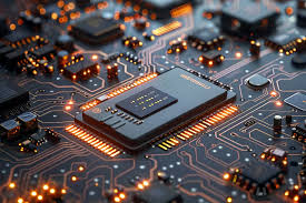
What is soldering in relation to a circuit board?
In through-hole soldering, component leads are inserted into holes drilled through the PCB, and solder is applied to the exposed leads on the opposite side of the board. This method was traditionally used for many electronic devices, as it provides strong mechanical support, making it ideal for components that may experience physical stress, such as connectors or large capacitors. Through-hole soldering is commonly done manually, though automated systems can be used in larger-scale production.
Surface-mount soldering (SMT), on the other hand, involves placing components directly onto the surface of the PCB without drilling holes. Surface-mount components are much smaller than through-hole components, allowing for more compact and dense circuit designs. Surface-mount technology is widely used in modern electronics, such as smartphones and laptops, where space is limited. Surface-mount soldering can be performed by hand for small repairs, but it is typically done using automated machines in mass production, where components are placed on the board, and the solder is applied using a reflow oven to heat the entire board evenly.
The material used for soldering is critical to the quality of the connection. Traditionally, solder was made from a mixture of lead and tin, which provided excellent melting properties and strong joints. However, due to health and environmental concerns associated with lead, lead-free solder is now commonly used in most electronics manufacturing. Lead-free solder typically contains a mixture of tin, copper, and sometimes silver, though it requires higher temperatures to melt and can be slightly more difficult to work with than traditional lead-based solder.