

rigid flex circuits handle vibration and shock
Rigid flex circuits are ideal for applications that require reliability, durability and flexibility in the smallest package possible. This hybrid technology combines rigid PCBs with flexible circuit substrates and eliminates the need for connecting wires to multiple systems in the product, allowing more room for component density. Rigid flex circuits also work well in environments where vibration and shock may be present. Medical imaging equipment, military missile guidance systems, automobile dashboards, sensors and driver assistance devices, all of which are often found in dynamic environments, benefit from rigid flex boards.
The fabrication process for rigid-flex PCBs starts with a dry film or liquid photoresist applied to the outer copper layers. The desired mask pattern is exposed and developed using lithographic imaging. Then, chemical etching selectively removes the unprotected copper to create the conductor traces. The etched circuit boards are then laminated together with the underlying FR-4 and/or polyimide layers. Mechanical drilling systems or laser ablation are used to create through holes, blind and buried vias spanning multiple layers, and wall plating deposits copper electroplating to establish the electrical interconnections. The plated holes are then soldered into place to complete the assembly.
Depending on the design of the rigid flex circuits board, stiffeners might be required to help stabilize the rigid sections. This is especially important for high-speed traces and signal layers. Stiffeners can be created from a wide range of materials, such as FR-4, high-reliability polyimide or metal. The PCB designer should identify the stiffeners in the fabrication drawing so that they can be applied to the appropriate regions of the flex circuit.
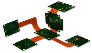
How do rigid flex circuits handle vibration and shock?
When the design of a rigid-flex circuit is ready to move forward, it’s time to prepare it for manufacturing. To ensure that the final rigid-flex circuit board meets all design requirements, it is critical to have the right PCB software at your disposal. The ideal software will allow you to define rigid-flex stackups easily and provide the CAD tools you need for the fabrication process. It should also support a variety of surface finishes and identifications to make it easier for you to communicate your design to your manufacturer.
Another important factor in designing a rigid-flex circuit is to understand that it will be subjected to bending, which can cause stress or damage to the circuit. To prevent this from happening, it’s best to keep key features like traces, vias and annular rings as large as possible. It’s also important to avoid sharp angles and tight features. Flex circuits are difficult to process, so tight features will require more attention and may not be as reliable as a traditional rigid circuit.
The best way to reduce the risk of a faulty rigid-flex circuit board is to work with a trusted manufacturer. Using a rigid-flex PCB that incorporates the latest technologies, fabrication techniques and materials, you can expect quality results that meet or exceed your expectations. Start your free trial of Altium Designer on Altium 365 today to see what this advanced electronics design software can do for you.